
An important part of Amateur Radio is that we have the ability to design and build our own radio equipment. However, getting started in this activity takes a ton of skills that seem to be hard to learn. One good way to jump-start this process is to build a radio from a kit. This allows the operator to learn proper build techniques while following the lead of a tried an true design. A typical starting point is to build a receiver with a low power transmitter. We’ve put together a kit that should let those that wish to take this step, succeed. We’ve chosen a small 40 meter 1/2 watt CW (morse code), circuit that will transmit, and receive on 7.030 MHz. This frequency is in the Technician band, so any licensed amateur operator can transmit and receive using this device. These QRP radios will allow the user to send and receive CW signals, with a good antenna, that could reach 120 miles.
The SCARS Homebrew team has put together the parts and created this document to help you build these radios. In addition, there’s a team of us that will help you gain the skills needed to build them. And, if something doesn’t work right, we’ll be there to help you diagnose the trouble.
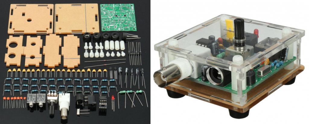
SCARS Pixie Kit
These kits are currently available for $10 from any SCARS officer. The SCARS kits are made up of the following pieces:
- The main circuit board and case kit, which includes most of the circuit pieces, case parts – This is the real core of the kit and contains all of the resistors, transistors, capacitors, connectors, and more. This kit also has 6 Lexan pieces that will be used as a case for the radio. eBay details
- 12-volt battery connections, 5.5 mm x 2.1 mm DC power connector. This is used to connect to a 12-volt power supply or battery. eBay details
- 9-volt battery connectors – The typical use case will be to power this radio with a 9-volt transistor battery. The additional 9-volt battery connector will be installed ‘after’ the full wave bridge, to allow better receive performance on a 9-volt battery. eBay details
- 3 pin SIP socket – This SIP socket will have the center pin trimmed, so you can slide the crystal in, and out, for future changes. eBay details
- 7.030 MHz crystal – The kit comes with a 7.023 MHz crystal. This frequency is in the “Extra Only” portion of the 40 meter band. This replacement crystal will let Technician and General operators transmit in their own portion of the band. eBay details
- Headphone with 3.5 mm plug – These earphones will let you hear the received signals. eBay details
- 3.5 mm plug for a CW key – This will let the operator connect a straight key to the Pixie radio. Pressing the key will turn on the transmitter. eBay details
- BNC female jack to an F connector – This will let the user connect an antenna using inexpensive, low-loss RG-6 coaxial cable. A simple dipole can be connected for better reception. eBay details
- BNC dummy load – This device will let the user transmit without damaging the transmitter. This will let the user send signals to a nearby short-wave receiver, or to another local transceiver. eBay details
Installation and User Operation Manual
The following Pixie User Manual can be used to help the build process of the Pixie radio. Using the circuit diagram should help the user figure out where each of the pieces and parts should go. Remember to dry fit the pieces to make sure you know you’ve got them set properly before you solder them in tight.
Skills Required
A number of skills are required to create this build.
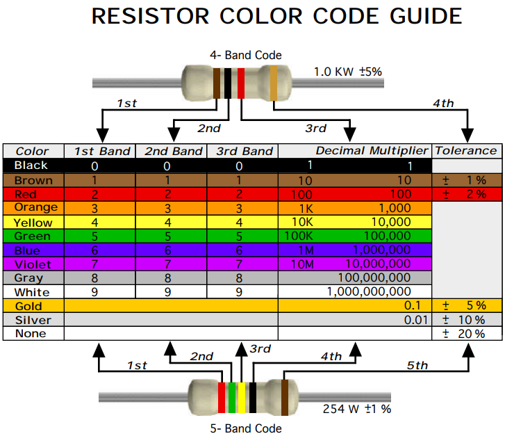
- Resistor color code – You’ll need to know how to read the colored bands on the resistors, to determine their value. Knowing their value will help you select the proper resistor to put in the proper slot. There’s a copy of the resistor color code in the Pixie User Manual.
- Reading a schematic – You’ll need to learn the schematic circuit drawing, and figure out which component goes into which holes on the printed circuit board. This design only has a limited number of parts, so this should be pretty easy. The circuit is in the Pixie User Manual.
- Capacitor number code – You will need to know how to read the capacitor values and make sure you select the proper capacitor for insertion into the board.
- Soldering – You’ll need to use a small soldering iron to solder the components to the bottom of the printed circuit board. Once you’ve applied a bit of heat to the board, and the component, you’ll add some solder to the joint. The solder will flow between the two pieces, and they will be connected, both electrically, and mechanically. For more information, please see the SCARS soldering page.
- Clipping the stray leads – You’ll use a diagonal wire cutter to clip the stray leads off the bottom of the board, once they’re securely soldered. Make sure you’re careful to hold the soon to be loose end, so it doesn’t fly across the room.
Tools Required
There are only a few small hand tools that are needed to finish this project. These will be available at ‘work nights’, or upon request from members of the SCARS Homebrew team:
- Soldering Iron
- Diagonal ‘side’ cutters
- Screwdrivers
- Small pliers
- Magnifying glass (for those of us of a “certain age”)
Circuit Drawing

How to Get Started Building Your Pixie Kit
The Heathkit projects of a day gone by had some great guidance on getting organized and staying that way. The first thing you should do is to create your workspace. One of those Heathkit tactics was to create a build box. This is an unused cardboard box that you can recycle for this purpose. A good box size for this project would be about 12″ x 12″ x 18″ long. Look at the photo below, and first trim off the top flaps, trim the front lip low and cut both sides at an angle. You can place the parts with leads into the tops of the cardboard edges to keep organized. Cutting the handhold in the back will let you move the build box when that need occurs.

Next, you’ll spend some time getting acquainted with parts from the kit. Start with the resistors. Using the color code below, and the parts list from the kit, place the resistors across the top of the box. Rank them from lowest to highest and you’ll be able to grab them quickly. Write the resistor values on the box, so you grab the correct one when you need them. Check off the parts as you load them into the top rail of the box.
The capacitors, inductors, diodes, and semiconductors all have numbers, so you can verify them against the parts list in the operators manual. Make sure to check off the parts as you place them in the box edges.
For the larger pieces and parts, grab an egg carton or two from the fridge and place the rest of the parts in the egg cups. Check the parts off of the list as you work through each one. Close the egg carton when you’re not using it so you don’t dump these parts on the floor. In this kit we’ve added a crystal socket, you’ll have an Extra only 7.023 MHz crystal, and a 7.030 MHz crystal for the Technician / Generals to operate legally.
Once you’ve got the parts identified and organized, you can start mounting them on the board. This process is usually called stuffing the board. Take a look at the circuit board, and you’ll see two different looking sides. The side that has all of the wording and part labels is the top, or part side, of the board. The other side is the bottom, or solder side, of the board. The general rule is that you mount the shortest parts first. Start with the resistors, diodes, capacitors, and inductors. Place each part, one at a time. Make gentle 90 degree bends in each part lead, and push them into the proper holes on the circuit board. Press the part into the top, or part side, of the board, and spread the leads on the solder side of the board to about 45 degrees, keeping the part from sliding out. Be very careful with the first part you place. Make sure you’re stuffing the board from the correct side.
Typically you place all of the parts of a given type, like all resistors, then double check that you’ve placed the correct resistors in the correct holes. Solder these parts in place, verifying that the solder has connected the board to the part and the piece is mechanically solid. Heathkit reports that 90% of their problems were caused by bad solder connections. Take your time. The assembly is the FUN part of these projects, don’t rush through it. When all of the leads have been soldered, use your side cutters to clip off the leads. Be careful when cutting the leads, hold the lead as you make the cut. If you don’t, the wire will fly across the room causing damage to your, or someone else’s eye.
Once you’ve done all of the resistors, repeat this process with the capacitors, inductors, diodes, transistors, crystal socket, LM386 socket, and all of the other items. Place the parts, verify their proper insertion, solder them in place, and clip the leads. Check off each part as you place them on the board. Between each type of part, take some time to inspect the board. Make sure all of the solder connections are solid and make sure there aren’t any solder bridges that make connections that shouldn’t be there.
Now, once you’ve built the Pixie kit, look around your work space. Having extra parts laying around is not a good thing. Install those extra parts, and start looking at the board. There are a couple of easy ways to goof up this kit.
- The first, would be to build on the wrong side of the PC board. It’s not that common to build the entire board, but it is easy to start putting a few parts on the wrong side.
- Second, carefully review the inductors. These look VERY similar to the resistors, and flipping some of these could cause some trouble.
- Third, make sure you have made good solder connections. It’s very easy to miss a few holes. Use a magnifying glass and check each connection. Touch up missing, or cold connections with your soldering iron.
- Fourth, look for stray wires, connections, and solder bridges on the board. Small solder beads may be left on the board and could cause trouble. Large solder blobs may connect two or more solder traces, which cannot be a good thing.
You’ll need to build the plastic case. It should be pretty easy to figure out the top and the bottom pieces. You’ll need to peel off the protective paper before you slot them all together. Before you power up the board, review all of the pieces, or have someone else review them. Connect the power connector to any DC power supply from about 9 VDC to 15 VDC. Connect the BNC dummy load device to the antenna port, connect the earphones, connect a Morse code key, and follow the operator manual instructions for running the radio.
Listen to the earphone, and you should hear some ‘hiss’. When you’re ready to transmit, press the key, and you should see the LED light up, the beeper will sound, and you should be transmitting on 7.030 MHz or 7.023 MHz, depending on which crystal you install. Turn on a separate receiver, and you should hear the tone.
Enjoy!
Circuit Operation
The Newport County Radio Club has done something similar with this circuit and has created some great documentation. This NCRC_PixieOperation presentation explains how the circuit works, and what each part of the circuit does.
CQ February 2018 Review
Our good friends at CQ magazine have jumped on board with this project kit, and have an article about this project in their February 2018 Issue – Pixie Transceivers Construction. KA8SMA has purchased a couple of these devices and has some good construction comments and an upgrade that includes a variable capacitor to let you move the frequency a bit.
Pixie History
In 1982, George Burt GM3OXX described the original circuit for the radio now known as the Pixie. More historical information is available at The_Sprat_Pixie_File.
Pixie Build Review
Amateur radio operator 4Z4TJ has created a nice little review of the Pixie kit and lists his thought in this Pixie Build Review.